


By Michael Matte (Circa 1985/1986/2019)


These five in-depth "packages" (documents) were created by Michael C. Matte in 1986. These documents explain how to upgrade a Bally Arcade/Astrocade from the "Consumer Mode," which uses the low-resolution display (160x102 pixels), to "Commercial Mode," which uses the high-resolution mode (320x204 pixels) used in arcade games such as Gorf and Wizard of Wor.
In a series of videos that Michael Matte began filming in March 2021, he gives overviews and insights into his high-res Astrocade hardware. These videos can be viewed on Michael's YouTube channel: MCMs Astrocades Videos
(Michael Matte).jpg) |
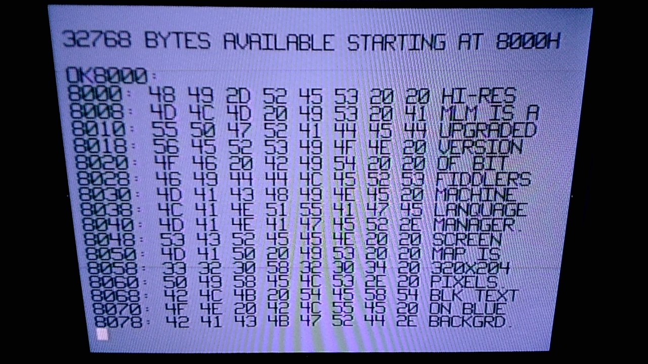
Hi-Res Astrocade Screenshot By Michael Matte. August 2017. In August 2017, Michael Matte continued to work on some projects with his Astrocade that he upgraded from the Bally's standard low-resolution (160x102) to High-Resolution (320x204) in the mid-1980s. Near the end of August 2017, he took a screenshot of a hi-res demo that he wrote to test the unit. For details about the picture, read this summary. |
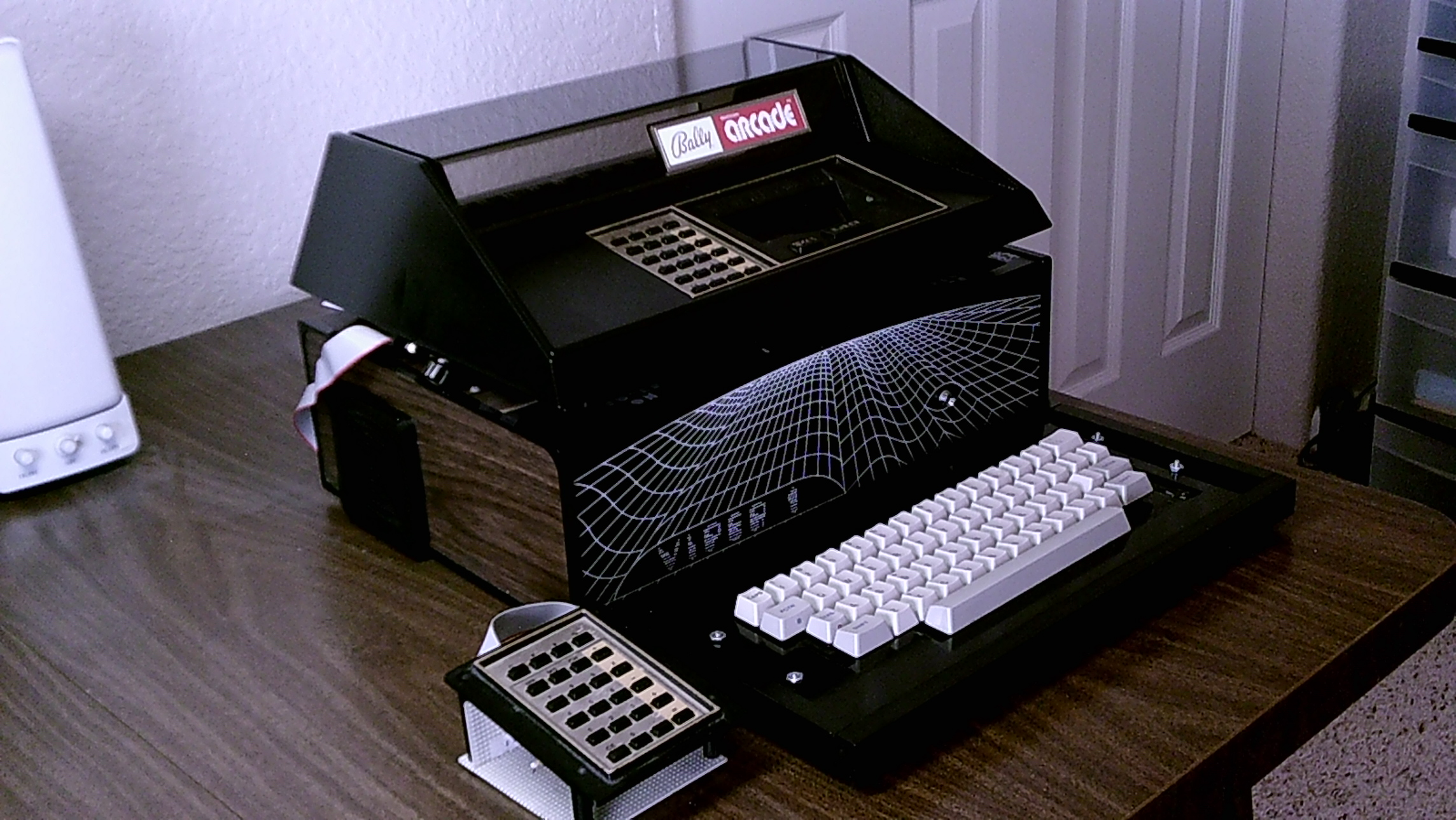 |
Michael's Hi-Res Astrocade System By Michael Matte. September 2017. Besides the obvious QWERTY keyboard addition, there is also an external keypad. Although the system has a Viper attached to it, that is only the case: the actual Viper hardware is not inside there, instead, it contains Michael's hi-res upgrade. |


|
Hi-Res Astrocade Screenshots By Michael Matte. September 2017. These are screenshots of Michael Matte's Hi-Res Astrocade. Included screenshots are of the low-res game Gunfight and the low-res menu running on a hi-res system. The final screenshot is a version of the MLM (Machine Language Monitor) cartridge that has been specially modified to work with the Michael's hi-res system. |
Initial Letters to Don Gladden and Bob Fabris
Michael Matte initially sent two letters to Don Gladden (who was the editor of Volume 6 of the ARCADIAN) and one letter to Bob Fabris (who replied to Michael's letters to Don). These letters talk about his work on his hi-res upgrade, other Astrocade-related projects and Michael expresses an interest in writing machine language tutorials for the ARCADIAN newsletter.
(June 7 and 8 1985)_tn.jpg) |
Letter to Don Gladden By Michael Matte. June 7 and 8, 1985. This letter has been OCRed and is available in text format: |
(Dec 21 1985)_tn.jpg) |
Letter to Bob Fabris By Michael Matte. December 21, 1985. This letter has been OCRed and is available in text format:
|
(Dec 26 1985)(Draft)_tn.jpg) |
Letter to Michael Matte By Bob Fabris. December 26, 1985. This handwritten letter (which is a draft-- Bob probably typed the final version of it) has been retyped and is available in text format:
|
High Resolution Package
These instructions were sent to Bob Fabris on July 3, 1986.
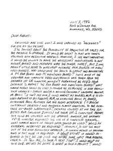 |
Hi-Res Package Cover Letter (to Bob Fabris) By Michael Matte. July 3, 1986. This two-page letter gives an overall view of the five packages. This handwritten letter has been retyped and is available in text format: |
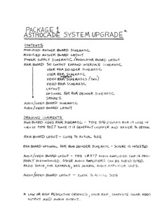 |
Hi-Res Package 1 - Astrocade System Upgrade By Michael Matte. "Package 1" of the Astrocade System Upgrade (low or high resolution graphics, user RAM, composite color video output and audio output) contains fifteen pages of schematics and layouts. Here is what is included in Astrocade Hi-Res Package 1:
|
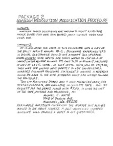 |
Hi-Res Package 2 - Low/High Resolution Modification Procedure By Michael Matte. Nineteen pages describing what and how to modify the Astrocade motherboard, plus how to wire the RAM board, which contains video and user RAM. It is assumed the user of this procedure has a copy of the Bally Service Manual PA-1. Beginning experimenters in digital electronics should not attempt this upgrade. Several unused gate inputs are shown wired to +5V via a 10K current limiting resistor allowing TTL chips to be occasionally substituted in lieu of LS TTL chips. If only LS TTL chips will be utilized, then wire the unused inputs directly to +5V (no resistor). Numbers following procedure statements indicate reference should be made to the note numbers, which are listed following the procedure. Two low resolution demos and a high resolution demo, for testing purposes, are available on cassette tape. Mail the request for the demos along with $7.00, to cover the cost of the tape, postage and packaging. |
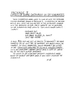 |
Hi-Res Package 3 - Copies of some Datamax UV-R1 Schematics By Michael Matte. These schematics were used to come up with the Astrocade system upgrade package 1. Comparison of the schematics will show the similarities of the Astrocade upgrade with the Datamax UV-1R. For a complete set of Datamax UV-1R schematics and layouts (excluding power supply) contact DataMax Inc. I paid $30 for one set of prints (21 drawings). The notes on the attached Datamax schematics were added by myself, way back when I was for studying the schematics. |
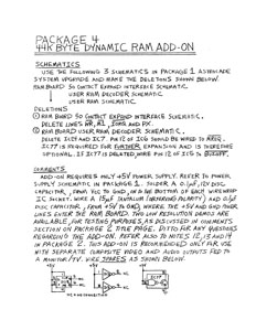 |
Hi-Res Package 4 - 44K Byte Dynamic RAM Add-On By Michael Matte. This one-page instruction sheet uses three schematics in "Package 1 Astrocade System Upgrade" to make some deletions for this upgrade. Add-on requires only +5V power supply. Refer to power supply schematic in Package 1. This add-on is recommended only for use with separate composite video and audio outputs between monitor/TV. |
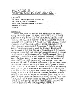 |
Hi-Res Package 5 - 12K Byte Static RAM Add-On By Michael Matte. Static RAM does not require any refreshing or special timing circuitry. Data will remain intact as long as +5V is supplied to the board and the write protect switch is on. This feature allows the board to be disconnected from one computer and connected to a second computer or allow cartridge swapping without running loops. In either case, the data in Static RAM will remain intact (unchanged). The Balcheck II display is optional and is used by Balcheck II software (not available at this time) to aid in troubleshooting the motherboard or static RAM. The videocade connector allows a videocade to be copied to tape. A videocade PC board, removed from its cartridge, is inserted in the videocade connector. Astrocade BASIC (or Bally BASIC) is then used to copy the contents of 6000-7FFFH to tape. Incidentally, this add-on can be used with the Package 1 upgrade (connected to 50-pin expand header). This add-on requires only a +5V power supply. This document is six pages of directions, schematics and layouts. |
High Resolution Schematics and Layouts
Since image files are compressed in a PDF document I have included some of the package schematics and layouts in PNG or TIFF uncompressed versions. Note that these uncompressed images are included in the original PDF documents. These uncompressed versions are for somebody that needs a really good look at the schematics because they are actually building the hi-res upgrade.
_tn.jpg) |
Hi-Res Package 1 Schematics in PNG Format Includes: Bally Motherboard Schematic, Bally Motherboard Layout, Video RAM Schematic and Video RAM Layout. |
_tn.jpg) |
Hi-Res Package 3 Schematics in TIFF Format Includes three schematics: CPU Board, Multiple Page Screen RAM, and "Video Board" Detail. |
_tn.jpg) |
Hi-Res Package 5 - 12K Byte Static RAM Add-On Schematics in TIFF Format Includes: 50-Contact Expand Interface Schematic, Balcheck II Display Schematic, Static Ram / Videocade Copier Schematic, and Layout. |
High Resolution Static Ram Upgrade (2019)
/MCM Design Hi-Res Static Ram Announcement (2019 09 11)(Michael Matte)_tn.jpg) |
MCM Design Hi-Res Static RAM Announcement September 11, 2019 RTF (Rich Text Format) Document MCM Design is pleased to announce a breakthrough in the high resolution RAM configuration for the 1970s Bally Arcade 3 custom chip set. Up to now, four 4KB banks of dynamic RAM were required to operate the 2 Bally custom address and data chips in the high resolution mode. Since each bank utilizes 8 DRAM chips, a total of 32 DRAM chips was necessary. However, MCM Design has developed, built and tested a prototype wire wrapped RAM board which can operate the same 2 custom chips in high resolution using only 4 static RAM chips. MCM Design's breakthrough static RAM configuration also offers single +5VDC power supply operation with optional user programmable multipage screen RAM capability. |
 |
High-Res Astrocade Machine Language Subroutines By MCM Design (Michael Matte). February/March 2020 and January 2021. PDF Document. The following high-resolution subroutines for the Bally Arcade/Astrocade were created by MCM Design and sent to Adam Trionfo as photocopies and text documents via email in February and March 2020. Adam compiled this collection of subroutines from ten documents in January 2021. It contains Z80 machine language subroutines for use with a modified-for-hi-res Bally Arcade/Astrocade home videogame console. The contents of this documents are:
The doc's intent is to help a hi-res programmer get started with custom programming hi-res graphic patterns and moving patterns around the screen without the need to create this particular hi-res application from scratch. These ML subroutines, except the custom subroutine example for MCM Design's hi-res multi-pager, function similar to their low-res equivalent. However, these hi-res subs must be called directly. There is no processing UPI (User Programmer Interface). Note, MCM Design's upcoming Hi-Res ROM will include sub's similar to these subs and will utilize a UPI. The ROM UPI and sub's will be well documented. Perhaps someday in the future, someone with machine/assembly language experience may acquire or build a modified hi-res Astrocade and might find this info useful. |
/Hi-Res Static RAM (2019 09 11)(MCM Design)(Astrocade)_01.jpg) |
Hi-Res Static RAM (Picture 1) Modified for Hi-Res astrocade connected to 4 bank static RAM. |
/Hi-Res Static RAM (2019 09 11)(MCM Design)(Astrocade)_02.jpg) |
Hi-Res Static RAM (Picture 2) High Resolution 320x204 Pixels Static RAM Board. |
/Hi-Res Static RAM (2019 09 11)(MCM Design)(Astrocade)_03.jpg) |
Hi-Res Static RAM (Picture 3) Modified for Hi-Res Astrocade Motherboard |
/Hi-Res Static RAM (2019 09 11)(MCM Design)(Astrocade)_04.jpg) |
Hi-Res Static RAM (Picture 4) MCM Design Software Hi-Res Test Routines and BalCheckHR (which includes Hi-Res Demos) |
(MCM Design)_tn.jpg) |
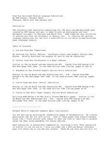
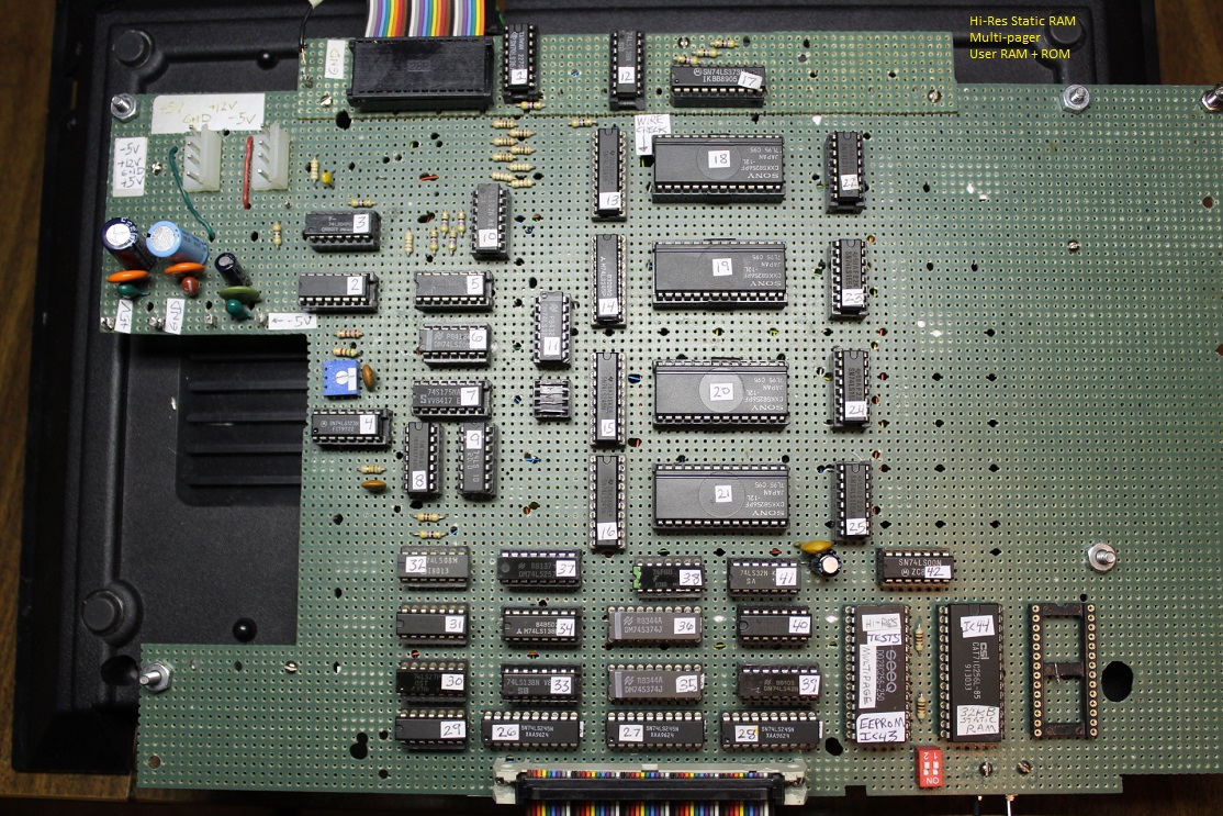
Bally Arcade / Astrocade Hi-Res Static Screen Ram Schematics By MCM Design (Michael Matte). September 20, 2019. PDF Document. Here is a brief overview of the Hi-Res Static Screen Ram Schematics:
|
 |
Astrocade Modified Hi-Res Motherboard (Picture 1) The Hi-Res project board with the optional user ROM/RAM scheme added. Note the total chip count has increased to 45 chips. That's a lot of chips. However, compare that chip count to the coin-op arcade Seawolf II. Keep in mind, that MCM Design's new hi-res static RAM Astrocade operates in low or hi-res, includes 8 pages of hi-res screen RAM (128KB) expandable to 16 pages (256KB) using a RAM board that operates off a single +5Vdc ($10) power supply. What a sweet set up. |
 |
Astrocade Modified Hi-Res Motherboard (Picture 2) The Hi-Res project board with the optional user ROM/RAM scheme added. |
(Michael Matte)_tn.jpg) |
Astrocade Hi-Res Multi-Pager Announcement. By MCM Design. June 2020. The 8KB Multi-Pager Test Demo package has been completed and runs as a standard Astrocade cartridge. All necessary hi-res routines reside within the test demo program package. No user RAM above 8000H is required to run the package. A standard low-res ROM (or custom 8KB ROM at 0000-1FFFH) is required only to jump to the test demo at 2000H. This 8KB package runs in hi-res only. It is intended for someone who is interested in modifying their Astrocade to utilize MCM Design's new hi-res SRAM scheme including the optional multi-pager scheme. This document is a RTF (Rich Text Format) file, not a pdf. It can be opened with most modern word processors. The 8K ROM file for the demo is not included here. Ten screenshots for the Demo Package can be downloaded.
|
 |
Hi-Res Multi-Page Test Demo - 8K Package Hand-Written Z80 Source Code. By MCM Design. December 2020. This is the 171-page, 88MB pdf document of hand-written documentation and Z80 source code for the 8KB Multi-Pager Test Demo. This program is a standard Astrocade 8K cartridge that runs on a modified Low/High-Res Astrocade with eight 16KB pages of SRAM (Static RAM) for a total of 128KB Screen RAM at a 320x204 pixel resolution each page. All necessary hi-res routines reside within the test demo program package. No user RAM above 8000H is required to run the package. A standard low-res ROM (or custom 8KB ROM at 0000-1FFFH) is required only to jump to the test demo at 2000H. This 8KB package runs in hi-res only. This 8KB package is self-containing. All necessary Hi-Res routines are included within the package. Lo-Res or custom ROM at 0000-1FFFh is required only to jump to 2000h. No user RAM 8000 -FFFFh is required. Hi-Res Screen RAM is addressed 4000-7FFFh. Magic RAM 0000-3FFFh. Refer to Nutting Manual for System Description Currently there is no ready-to-assemble source code for this program, but the cartridge ROM image can be downloaded:
|
 |
Perkins Medium-Res Mode: A Commentary By MCM Design. December 16, 2021. RTF (Rich Text Format) Document. This document will give the reader a fundamental grasp of the Perkins medium-resolution theory of operation. Med-Res is a mode which is only available on the Perkins Hi-Res unit; the Astrocade chipset does not support it natively. |
(Michael Matte)_tn.jpg) |
Third and Final Hi-Res Astrocade Prototype. By MCM Design. February 17, 2021. MCM Design's vision for its final low/hi-res static screen RAM (SRAM) Astrocade, a wire wrapped prototype with a 3 board add-under. The three boards are: Board 1: Static Screen RAM (SRAM) Board, Board 2: User ROM/RAM Board and Board 3: Pattern Transfer Board.
|
