


By Michael Matte (Circa Mid-1980s)


More information about Michael Matte's high resolution Astrocade can be found here:
Michael continues to work on this project as of August 2018. Here are the plans that he sent along with ten of the pictures below.
Michael has written brief descriptions for each picture of his high-res Astrocade. These descriptions are next to the picture below. Michael has written a "tour" that provides detailed information on MCM Design's low/hi-res Astrocade for anyone desiring to take the challenge and build such an Astrocade. The details may help provide ideas for creation of someone's own version of a hi-res Astrocade.
In a series of videos that Michael Matte began filming in March 2021, he gives overviews and insights into his high-res Astrocade hardware. These videos can be viewed on Michael's YouTube channel:
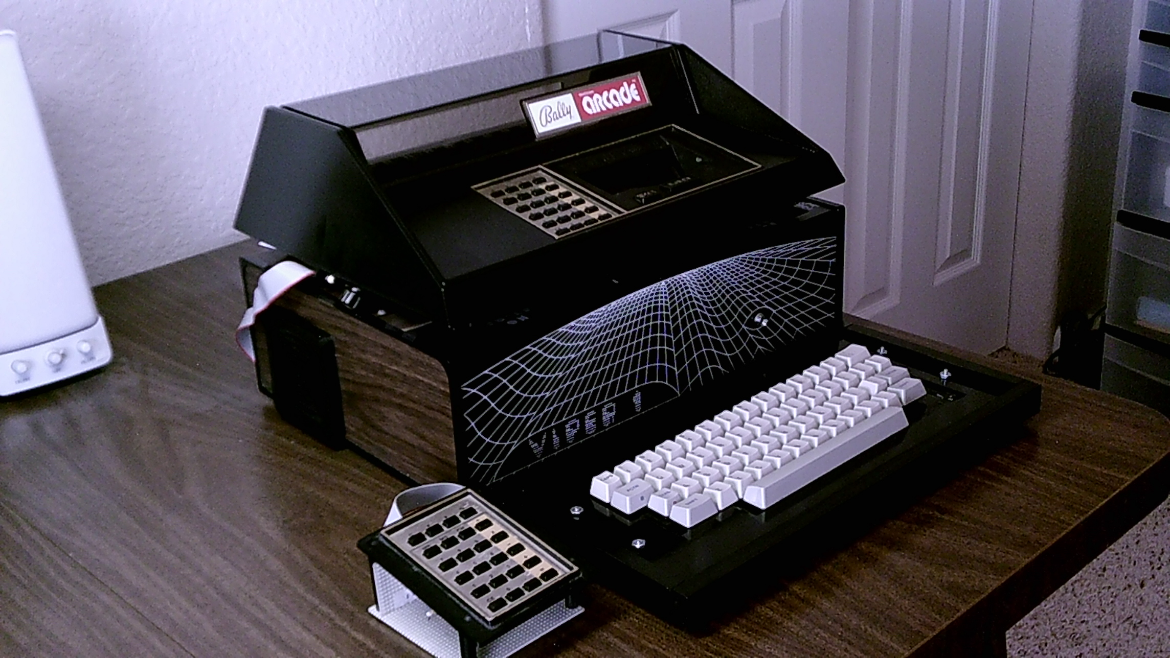 |
Michael's Hi-Res Astrocade System - Picture 0 By Michael Matte. September 2017. MCM Design's low/hi-res Astrocade is mounted on top of a (previously empty) Viper 1 cabinet. The Astrocade has an interface for a full-size QWERTY matrix keyboard and a connector for a custom 24 button keypad. |
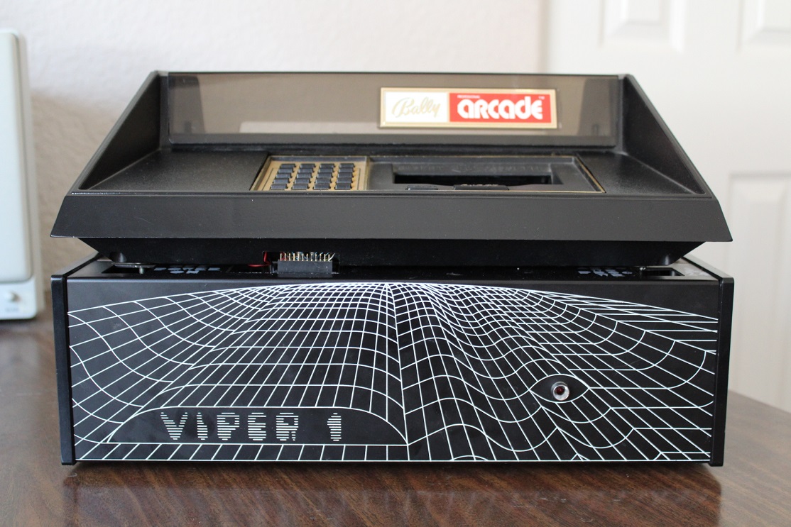 |
Michael's Hi-Res Astrocade System - Picture 1 Front view shows 24-pin wire-wrapped socket mounted on modified motherboard for ribbon cable connection to the low/hi-res screen RAM interface inside the Viper cabinet. |
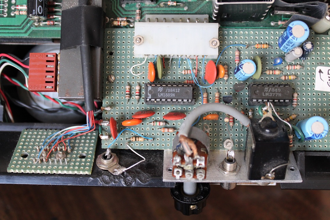 |
Michael's Hi-Res Astrocade System - Picture 2 Top view of custom audio/video board providing 2 audio outputs and composite video output. Remote keypad connector is also visible on the left. |
 |
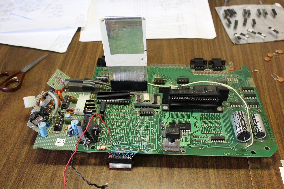
Michael's Hi-Res Astrocade System - Picture 3 View of Astrocade and ROM/RAM board assembly, hinged to back of Viper cabinet, when swung up and back. |
 |
Michael's Hi-Res Astrocade System - Picture 4 Front view of ROM/RAM board showing 24-pin ribbon cable on top and 50-pin ribbon cable on the bottom. |
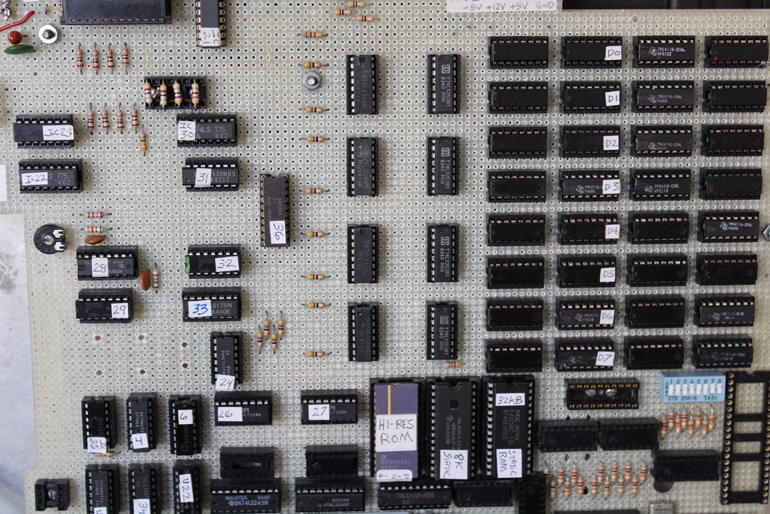 |
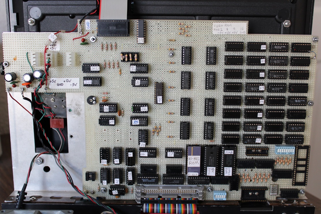
Michael's Hi-Res Astrocade System - Picture 5 Closer front view showing four 4KB screen RAM banks on the right, 2 static user RAM chips, one 8KB hi-res ROM chip and all the necessary interfacing chips. |
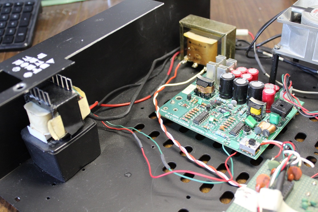 |
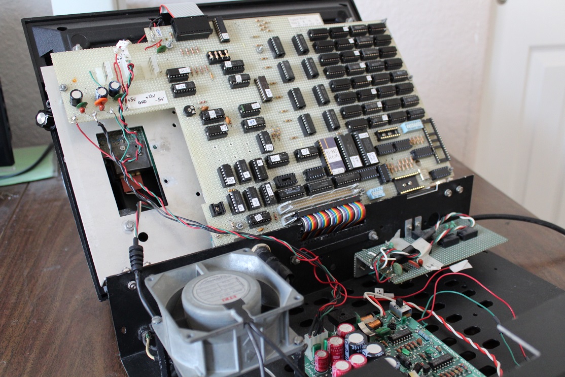
Michael's Hi-Res Astrocade System - Picture 6 Viper cabinet interior showing exposed Astrocade pwr xfmr, ROM/RAM board pwr xfmr, +5V,+12V,-5VDC power supply board and forced air cooling fan for Astrocade motherboard. |
 |
Michael's Hi-Res Astrocade System - Picture 7 Top view of modified motherboard with audio/video board and remote keypad connector. |
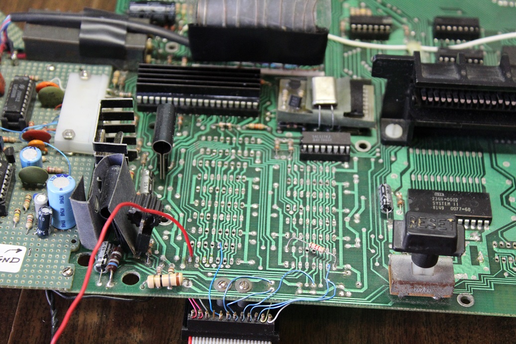 |
Michael's Hi-Res Astrocade System - Picture 8 Closer view of motherboard showing 6 blue custom chip address lines MA0-MA5 from top of motherboard to 24pin ribbon cable socket. Low-res RAM chips are removed. |
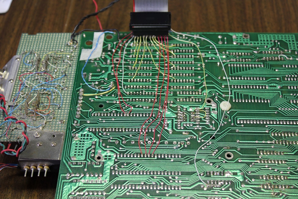 |
Michael's Hi-Res Astrocade System - Picture 9 Bottom view of motherboard showing 17 necessary connections from motherboard to RC socket. See Tour Description doc for details. |
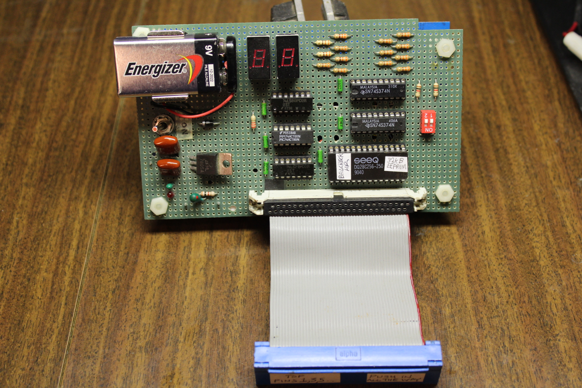 |
Michael's Hi-Res Astrocade System - Picture 10 Top view of new upcoming BalCheckHR board shows 5 TTL (or compatible) chips with multicarted 32KB EEPROM. Solder contacts for remote power supply are underside. |
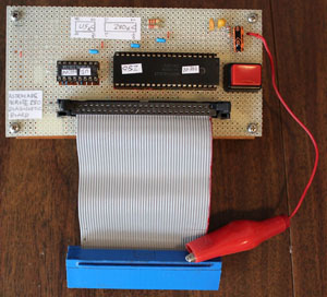 |
Remote Z80 CPU Diagnostic Board. By Michael Matte. September 2021. Four photos of the remote Z80 CPU wire wrapped prototype board. Allen Schweitzer now owns this cool diagnostic tool.
|
